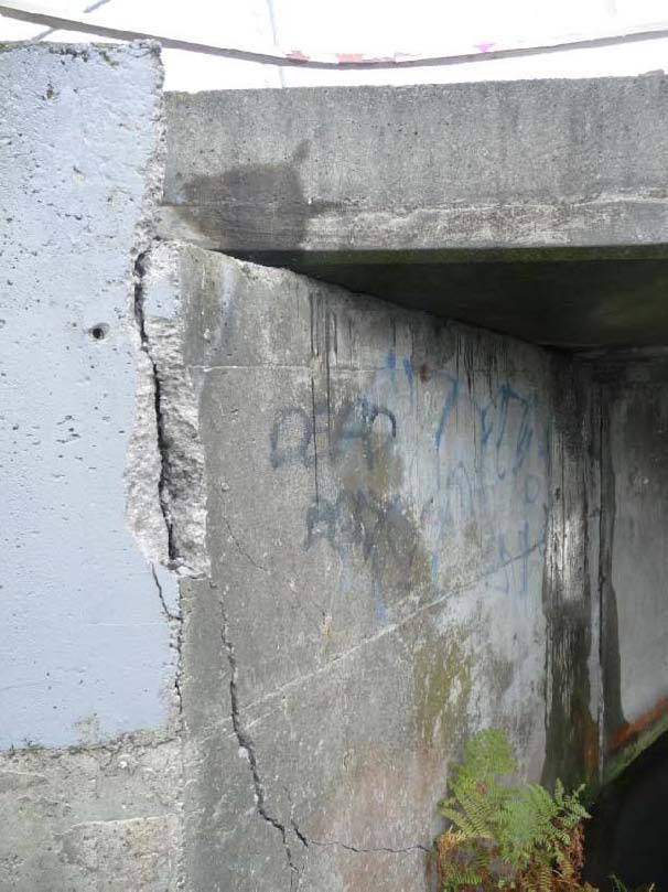
Regarding this third point, Figure 1a‐c shows the Gayhurst Road bridge over the Avon river in Christchurch, in a neighborhood where extensive soil liquefaction took place. River banks had multiple sand boils, the ground surface exhibited many large open cracks due to lateral spreading of the soil, and many residential homes suffered extensive damage due to differential settlements. At that location, in spite of this extensive liquefaction and soil movements, that bridge did not suffer any significant structural damage, except for abutments where vertical cracks in the wall at the edge of bridge deck width developed under the applied soil pressures. This can be explained by the sturdy monolithic structure of this bridge, in both its longitudinal and transverse directions; wide wall piers provided a stiffness and strength largely in excess of the values needed to resist severe seismic excitations transversely to the axis of the span, and continuity of the superstructure from abutment to abutment provided a rigid behavior in the longitudinal direction. Note that while the bridge’s wall piers were likely supported on piles, damage to such piles would be difficult to identify if at all present (this would incidentally be the case for all the bridges inspected as part of this earthquake reconnaissance visit).
The longer Bridge Street bridge connecting South Brighton to Christchurch behaved similarly, with the difference that, in this case, the lateral forces due to lateral spreading at the abutments rotated those abutments about a contact point at the slab level, resulting in a residual rotation of the abutments as well as distortion and sliding of the neoprene bearings (as seen in Figure 2a‐c) – the original location of the bearings could be clearly seen on top of the abutments at the point of girder supports (Figure 2d‐e). As a result soil lateral spreading and settlement, both abutments moved closer to each other, the West Abutment (from Bexeley Road) moving in contact with the deck.
Some bridge not endowed with similar strengths and stiffnesses to resist the demands applied to them as a consequence of the liquefied soils did not fare as well. For example,
The Mandeville pedestrian suspension bridge in Kaiapoi, built in 1874 [4] over the Waimakarini River, also suffered substantial damage when one of its towers rocked longitudinally beyond the point of stability above its support, resulting in a downward span failure in the direction of the falling tower, and concurrent beam fractures in the opposite upward moving span (Figure 6a‐b). Cursory inspection of the steel connectors between the timber towers and its supporting timber pile bents did not lead to a clear understanding of the mechanism providing stability to the structure under normal unbalanced load conditions. Lateral spreading may have also partially contributed to this
failure, albeit in a secondary way.
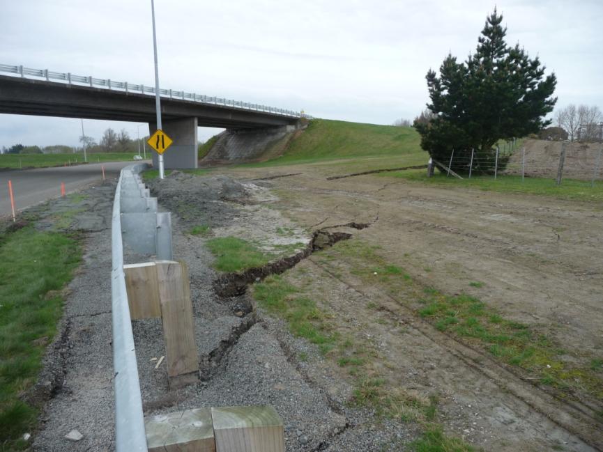
In some instances, while the bridges remains essentially intact, the approach spans partially or totally failed, making access to the bridge more difficult or impossible. For example, the twin continuous bridges at the Chaney overpass on Highway 1 north of Christchurch were found to be structurally sound, and tied to their abutment walls to prevent unseating there. However, due to liquefaction at the site surrounding the bridge, the approach to the southbound lanes of that Highway 1 settled by a few inches (Figure 7a‐b). After a brief closure for inspection, this busy route was reopened with signage reducing the speed to 30 km/h (down from 100km/h) for the safety of motorists driving across that bridge.
The approach to the River Bridge, in Lincoln (approximately 8 miles from the fault), exhibited a dramatic evident of settlement from its original perfectly horizontal alignment (Figure 8a). Again, cracks in the approaches parallel to the axis of the bridge provide evidence of the resistance against lateral spreading provided by this short monolithic span (Figure 8b).
Many bridges at similar distance (or closer to the fault), where soil liquefaction did not occur, did not suffer damage. For example, the Highway 1 bridge across the Selwyn river (Figure 9a), less than 3 miles from the fault, and the railroad bridge adjacent to it, were operational. As the main North‐South route from Christchurch to south of the island, this bridge consisted of multiple simply supported spans tied together in pairs using reinforced steel wedges over wall piers supported on piles (Figure 9b). Note that similar ties were observed in many other bridges on major thoroughfares, such as the Avondale Rd Bridge in Christchurch shown in Figure 10 for example.
Finally, note that soil settlement and lateral spreading at bridge abutments often detrimentally affected the utilities carried by those bridges. For example, fracture of a sewer pipe across the Pages Rd Bridge near Brooklands north of Christchurch, contaminated the river (Figure 11a‐b). Incidentally, flexural cracks were observed on the abutment piles exposed as a consequence of soil lateral spreading (Figure 11c).
 |
 |
 |
|||
| Figure 1a. Bridge on Gayhurst Rd, global view (Photo by M. Bruneau) | Figure 1b. Vertical crack on west side of north abutment (M. Bruneau) | Figure 1c. Vertical crack on east side of north abutment (M. Anagnatopoulou) | |||
 |
 |
 |
|||
| Figure 2a. Bridge St bridge, Christchurch; West abutment rotation (M. Anagnatopoulou) | Figure 2b. Close-up of abutment rotation (M. Anagnotopoulou) | Figure 2c. Close-up of pile at abutment rotation (M. Anagnotopoulou) | |||
 |
 |
 |
|||
| Figure 2d. Displacement of elastomeric bearing, north edge of west abutment (M. Bruneau) | Figure 2e. Displacement of elastomeric bearing, south edge of west abutment (M. Anagnotopoulou) | Figure 3a. Pedestrian bridge, River Rd – Avonside Dr, Christchurch (M. Anagnotopoulou) | |||
 |
 |
 |
|||
| Figure 3b. Pedestrian bridge, River Rd – Avonside Dr, Christchurch (M. Anagnotopoulou) | Figure 4a. Pedestrian bridge, Christchurch; Global view (M. Anagnotopoulou) | Figure 4b. Spalling and rebar buckling at mid-span (M. Bruneau) | |||
 |
 |
 |
|||
| Figure 5a. Pedestrian bridge, Kaiapoi (M. Anagnotopoulou) | Figure 5b. Pedestrian bridge, Kaiapoi (M. Anagnotopoulou) | Figure 5c. Pedestrian bridge, Kaiapoi (M. Anagnotopoulou) | |||
 |
 |
 |
|||
| Figure 6a. Mandeville bridge, Kaiapoi (M. Anagnotopoulou) | Figure 6b. Mandeville bridge, Kaiapoi (M. Anagnotopoulou) | Figure 7a. Chaneys Overpass, HW1 (M. Anagnotopoulou) | |||
 |
 |
 |
|||
| Figure 7b. Chaneys Overpass, HW1 (M. Anagnotopoulou) | Figure 8a. River Bridge, Lincoln (M. Bruneau) | Figure 8b. River Bridge, Lincoln (M. Bruneau) | |||
 |
 |
 |
|||
| Figure 9a. Highway 1 bridge over Selwyn River (M. Bruneau) | Figure 9b. Highway 1 bridge over Selwyn River (M. Bruneau) | Figure 9c. Highway 1 bridge over Selwyn River (M. Bruneau) | |||
 |
 |
 |
|||
| Figure 10a. Avondale Rd Bridge (M. Bruneau) | Figure 10b. Avondale Rd Bridge (M. Bruneau) | Figure 10c. Avondale Rd Bridge (M. Bruneau) | |||
 |
 |
 |
|||
| Figure 11a. Pages Rd Bridge, Brooklands (M. Bruneau) | Figure 11b. Pages Rd Bridge, Brooklands (M. Bruneau) | Figure 11c. Pages Rd Bridge, Brooklands (M. Bruneau) | |||
[1] Professor, Dept of Civil, Environmental, and Structural Engineering, University at Buffalo, Buffalo, NY
[2] SEESL Structural Engineer, Dept of Civil, Environmental, and Structural Engineering, University at Buffalo, Buffalo, NY
[3] Senior Lecturer in Structural Engineering, Dept. of Civil and Natural Resources Engineering, University of Canterbury, Christchurch, New Zealand
[4] Historic Kaiapoi and Mandeville Bridge