James M. Ricles, Professor, Lehigh University, Bethlehem, PA, USA (Group Leader)
Dimitrios G. Lignos, Assistant Professor, McGill University, Montreal, Canada
Jay Love, Degenkolb Engineers, San Francisco, CA, USA
Mitsumasa Midorikawa, Professor, Hokkaido University, Japan
Taichiro Okazaki, Associate Professor, Hokkaido University, Japan
|
|
||
| Figure A. EERI Steel Structures Reconnaissance Group (from left to right: Prof. Taichiro Okazaki, Prof. Mitsumasa Midorikawa, Mr. Jay Love, Prof. Dimitrios Lignos, Prof. James Ricles). | ||
Day 1 (June 2, 2011)
After arriving in Tokyo during the evening we had a briefing at the AIJ headquarters by Prof. Midorikawa and Prof. Okazaki. We were informed about the areas of reconnaissance as part of our trip and the major earthquake and tsunami damage on steel structures in the Sendai area. Our reconnaissance effort focused around the following areas: Tohoku University, Oroshimachi and two of the main fishing ports the Ishinomaki and Onagawa that were affected by the tsunami during the 2011 Tohoku earthquake in Japan.
After taking the Shinkansen from Tokyo we arrived to Sendai around 11:00am. Our first stop was in Tohoku University. Dr. Mosato Motosaka, Professor of Earthquake Engineering and Structural Dynamics at Tohoku University was our host. We visited several buildings located on campus that were damaged during the earthquake. The main observations from steel, composite and reinforced concrete buildings retrofitted with steel braces are summarized as follows:
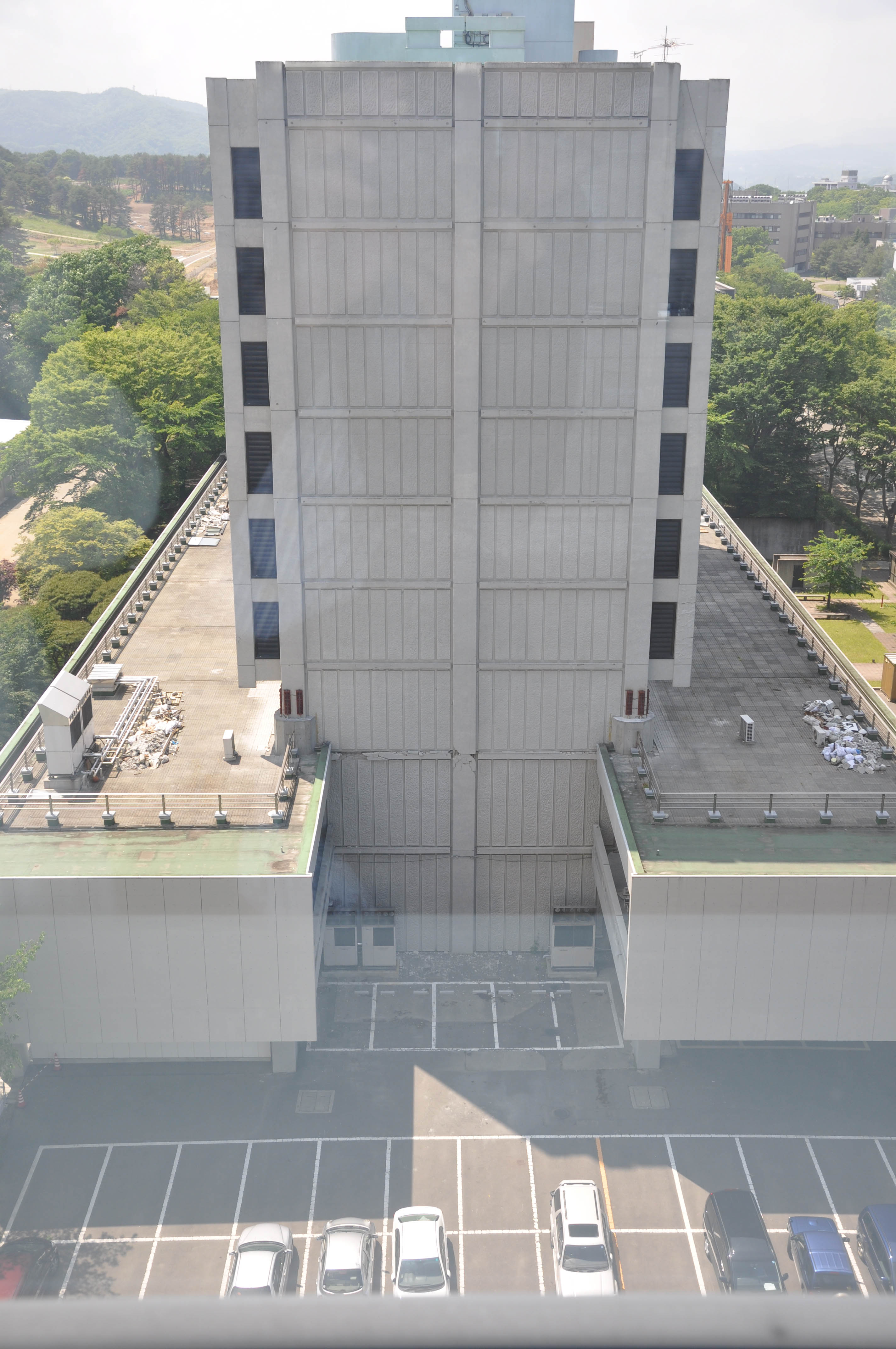
Architecture Building: This is a 9-story steel-reinforced concrete building with three podium levels (see Figure 1). This building was damaged during the 1978 Miyaki-ken Oki earthquake. After the 2003 earthquake in the same region the building was retrofitted with steel braces (see Figure 3). After the 2008 earthquake the university installed a long time monitoring system to measure changes in stiffness over time. Prior to the 2011 earthquake, this building had a predominant period of about 0.6sec. The earthquake damage was concentrated at the vertical boundary elements of the transverse concrete shear walls at the transition floor from the tower to the podium level.
 |
 |
|
| Figure 1. Architecture building. | Figure 2. Seismic retrofit of the exterior columns of the architecture building. | |
 |
| Figure 3. Steel braces as part of the 2003 seismic retrofit of the architecture building in Tohoku University. |
The period elongation of the building during the 2011 earthquake was about 1.3sec. The building was recently retrofitted with longitudinal concrete walls at the corners (see Figure 2).
Applied Chemisty and Chemical Engineering Building: This is a reinforced concrete construction, which was retrofitted with steel braces in the past as shown in Figure 4. This building had no indication of damage after the 2011 earthquake.
|
|
| Figure 4. Applied chemistry and chemical engineering building. |
New Civil Engineering Building: The 13-story building, which is shown in Figure 5 consists of steel MRFs. Its steel columns are encased with reinforced concrete (see Figure 6). This building performed very well during the March 2011 earthquake. It should be pointed out that the building is equipped with oil dampers. One of these dampers is shown in Figure 7. The maximum absolute acceleration at the roof of the building was about 1g during the 2011 earthquake. However, only non-structural damage was reported in the building.
 |
 |
 |
| Figure 5. New Civil Engineering (CEE) Building. | Figure 6. Steel column encased with reinforced concrete. | Figure 7. Oil damper installed in the CEE building. |
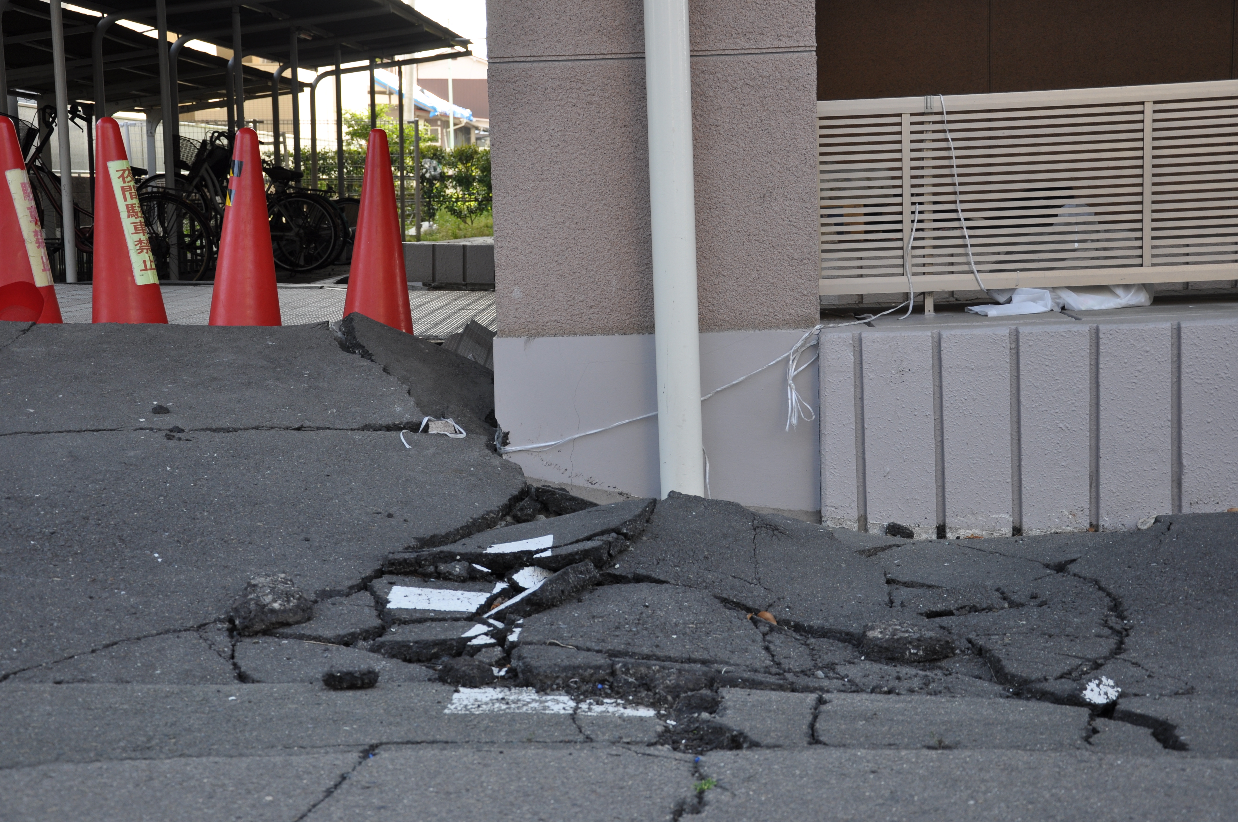
During our route to the coast we visited a 13-story steel encased reinforced concrete building (SRC) at Sunny Heights. This building was designed in 1976 with pile foundation due to bad soil conditions in this area. The primary structural system consisted of composite moment resisting frames. During the main event (Mw=9.0) the residual roof displacement was 70cm (~1.3% rad) and after the main aftershort of April 7th (Mw=7.4) the residual roof displacement of about 2% rad (see Figure 8). The bad performance of the foundation (soil liquefaction as shown in Figure 10) “helped” the building not to collapse. The building had several shear cracks in non-structural components as shown in Figure 9. Note that opposite to this structure there was a 7-story light-gauged pre-fabricated building with reinforced concrete footing (i.e. no piles) that performed very well during the earthquake.
 |
 |
| Figure 8. 13-story SRC residential building (residual roof drift of about 2%). | Figure 9. Shear cracks to non-structural components of the 13-story SRC building. |
 |
| Figure 10. Soil foundation problems due to liquefaction (13-story SRC condominium). |
| |
Our next stop was in the coast. There were several steel buildings with their primary lateral system being a steel MRF that survived the earthquake followed by the Tsunami. The average height of the steel buildings in this area ranges from 2 to 4-stories. Typical failure modes in industrial buildings such as the one shown in Figure 11 included exposed column base failure and twisting of deeper steel columns due to ramming (Figure 12). Note that in this area there are several steel buildings with cover plate connections and W shape columns. This indicates old japanese steel construction since the modern ones are typically built with hollow square sections (HSS).
 |
 |
 |
|||
| Figure 11. Steel industrial building partially collapsed due to ramming. | Figure 12. Twisting of steel beams and columns due to ramming. | Figure 13. Horizontal X-bracing to guarantee diaphragm action. | |||
Another characteristic of the steel buildings that survived the Tsunami is the fact that the floor diaphragm action is guaranteed with horizontal X-bracing (see Figure 13).
2-story industrial building: The building shown in Figure 14 had a residual drift of about 4% in the East-West (EW) loading direction. In the same direction, there was indication of earthquake damage due to flange local buckling of the steel beams near the beam-to-column connections at top and bottom location as shown in Figure 15. This building also experienced panel zone inelastic deformation as shown in Figure 16. In the other loading direction (North-South) the primary lateral system was a braced frame. Net section fractures were observed in this case (see Figure 17). The residual deformation of the steel building in the NS direction was about 1.25%.
|
|
| Figure 14. 2-story steel industrial building with a complete 2 story collapse mechanism. |
 |
 |
 |
|||
| Figure 15. Local buckling of the bottom flange of the first floor steel beam of the 2-story steel industrial building. | Figure 16. Panel zone shear distortion (2-story steel industrial building). | Figure 17. Steel X-brace in the NS loading direction of the 2-story steel industrial building. | |||
At the end of the day we joined Prof. Kasai’s group and Prof. Motosaka gave us a briefing of the earthquake related damage in Tohoku University and Oroshimachi area during the 2011 Off Pacific Coast Tohoku earthquake.
During the third day we visited the Onagawa fishing port , which is shown in Figure 18. This area was primarily damaged from the Tsunami that followed the earthquake. We visited several industrial steel buildings located in the area. The steel buildings in this area range from 2 to 5 stories.
|
|
| Figure 18. Onagawa fishing port. |
2-story industrial steel building: The building shown in Figure 19 consists of a 1-bay steel moment frame in the NS loading direction with cover plate moment connections and a 4-bay braced frame in the EW loading direction. Due to wave pressure a second story sway mechanism was developed due to weak axis column bending as shown in Figure 20. This resulted to excessive local buckling at the bottom of these columns as shown in Figure 21. When the steel braces of the second story fractured the sway mechanism was developed.
 |
 |
||
| Figure 19. 2-story steel building with 2nd story collapse mechanism due to lateral water pressure. | Figure 20. 2nd story column weak axis bending due to lateral water pressure. | ||
 |
| Figure 21. Local buckling of the steel columns at the 2nd story of the steel structure. |
3-story restaurant building: The 1×3 bay steel building shown in Figure 22 has steel moment resisting frames as the primary lateral resisting system in both loading directions. Due to the Tsunami wave the building developed a 3-story sway mechanism shown in the same figure and had a residual deformation of about 6% in the first story. This building was designed before 1981 since its beam-to-column connections include fins that were welded in the field. All the connections of the 3-bay steel MRFs fractured (see Figures 23, 24). Base plate uplift was in the order of 4cm as shown in Figure 25.
|
|
| Figure 22. 3-story steel moment resisting frame with a 3-story complete collapse mechanism. |
 |
 |
 |
|||
| Figure 23. Weld fractures at the interior fin beam-to-column connection of the 3-story restaurant building. | Figure 25. Base plate uplift (3-story restaurant building). | Figure 24. Weld fractures at the exterior fin beam-to-column connection of the 3-story restaurant building. | |||
3-story steel industrial building: The building shown in Figure 26 was a 4×4 bay 3-story steel building with steel MRFs in both loading directions. The building had 30x30cm tubular columns and modern japanese connections (see Figure 27) therefore the design is post 1981. The diaphragm action was guaranteed through horizontal x-bracing as shown in Figure 28. Excluding the exterior cladding the main structural system performed well during the earthquake and tsunami. In summary, steel buildings that were designed based on older japanese seismic provisions around the area and survived the tsunami had minor damage due to uplift of their base plates.
 |
 |
|||
| Figure 26. 3-story steel industrial building that survived the tsunami in the Onagawa area. | Figure 27. Typical beam-to-column connection of a modern japanese steel construction. | |||
 |
| Figure 28. Horizontal x-bracing per floor (3-story steel industrial building). |
Toppled Buildings: There were at least 5 buildings (both steel and RC buildings) with pile foundations that toppled over due to the water pressure from the tsunami. An example of those buildings is shown in Figure 29 that shows a 3-story steel building. The pile foundations of the same building were damaged due to overturning as shown in Figure 30. At least 4 more buildings toppled over due to the wave pressure (see Figures 31).
 |
 |
 |
||||
| Figure 29. 3-story steel building with pile foundation that toppled over due to the water pressure. | Figure 30. Foundation of 3-story steel building (piles failed in tension). | Figure 31. Toppled reinforced concrete building (Onagawa port). | ||||
After leaving the Onagawa port, on our way to the fishing market we visited a school gymnasium designed in 1970s (see Figure 32). This building consisted of steel braces (angles) in EW loading direction. Some of these braces buckled during the earthquake (see Figure 33). The roof of the building had sag rods. Almost 90% of these rods were damaged due to bold fracture in shear (see Figure 34).
|
|
| Figure 32. School gymnasium with steel braces designed in 1970s. |
|
|
 |
| Figure 33. Buckled X-brace of the steel gymnasium. | Figure 34. Damaged sag rods at the roof of the school gymnasium. |
In the fishing market several steel industrial buildings were damaged due to the tsunami. When we arrived to the fishing market there was a street construction going on since part of the fishing market was sunk about 70cm due to the earthquake.
The front entrance (facing the sea) of the 1-story steel industrial building shown in Figure 35 was not damaged at all compared to the back portion, which is shown in the same figure. The reason was that the water came inside the building from the bottom and the water pressure destroyed the concrete floor (see Figure 36). Several column base rods of the back entrance fractured and steel columns failed due to lateral torsional buckling as shown in Figure 37.
 |
 |
 |
| Figure 35. One story steel industrial building in the fishing market. | Figure 36. Cracked concrete slab from the water pressure. | Figure 37. Lateral torsional buckling of a steel column due to impact. |
Several steel buildings that did not collapse due to the tsunami had excessive damage at exposed base plates. Typical failure modes included rod fracture due to tension and uplift of the base plate. Figures 38, 39 and 40 are representative examples that illustrate these failure modes.
 |
 |
 |
| Figure 38. Column base rod fracture due to overturning. | Figure 39. Column base uplift. | Figure 40. Column base uplift. |
Around the fishing market, several old steel industrial buildings with heavy equipment consisted of diagonal angle steel braces. Net section fracture occurred in most of these braces as shown in Figure 41.
 |
| Figure 41. Net section fracture of a steel brace (steel industrial buildings). |
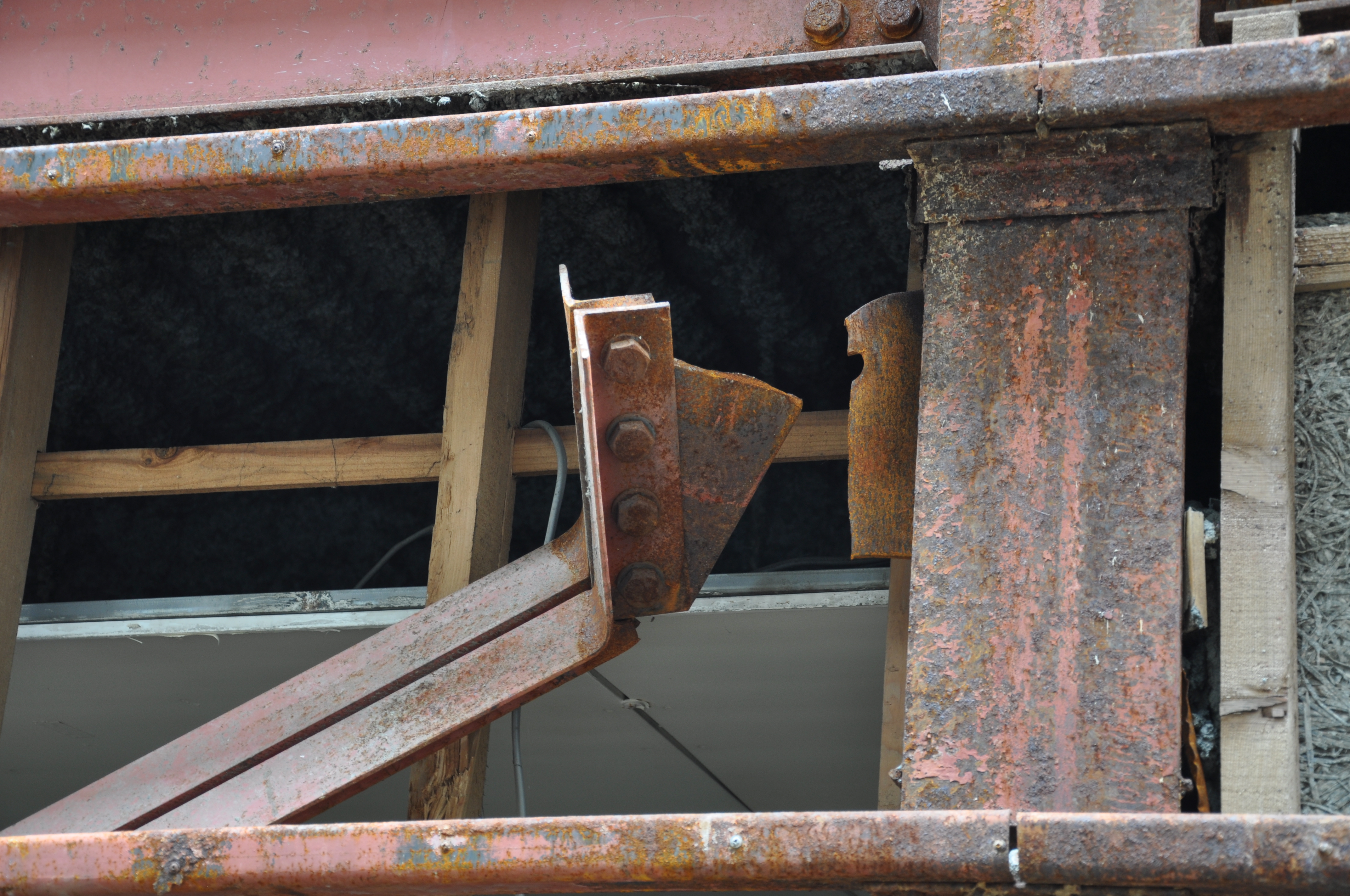
On our way back to the hotel we crossed a heavy industrial zone close to the fishing market. One of the steel buildings that was damaged consisted of 12 spans in the longitudinal loading direction but 2 of those were missing due to ramming (see Figure 42). The building had tie rods as vertical bracing that failed at the base due to bold shear failure (see Figure 43). The residual drift of this building in the longitudinal loading direction was about 0.23% rad. Uplift was also observed in several base plates of the building. Based on observations at the roof something pushed the roof girder in the longitudinal loading direction and caused the residual deformation discussed earlier. Other industrial buildings in the area designed with slender W24 steel columns were primarily damaged due to column twisting (see Figure 45) and base plate uplift.
 |
 |
||
| Figure 42. Steel industrial building damaged by impact. | Figure 43. Bolt fracture at tie rods. | ||
 |
|
||
| Figure 44. Bending of the steel girder at the roof of the steel industrial building due to impact. | Figure 45. Lateral torsional buckling of a W24 column due to impact at about mid-height. | ||
Our last stop during day 3 included the building shown in Figure 46, which is a management and safeguard building. This building had a pile foundation because of bad soil conditions of the fishing market area. As shown from Figures 47 and 48, liquefaction caused scouring and everything flowed around the building.
 |
 |
 |
| Figure 46. Management and safeguard building. | Figure 47. Pile foundation #1 after liquefaction. | Figure 48. Pile foundation #2 after liquefaction. |
In the same street there was one more building that its pile foundation had similar problems with the ones shown in Figures 47 and 48.
During the last day of our trip we mostly visited residential steel or composite buildings and steel parking garages located in the Oroshimachi area that were mostly damaged due to earthquake shaking. The main structures that we visited are summarized as follows:
11-story SRC building: The building shown in Figure 49 is located in the K-Q plaza and was designed on pile foundation in 1975. The steel columns of this building are encased with concrete all the way up to the last story since the building height is above 21m (design regulation in the Sendai area). The 11-story SRC building has a U-shape plan view and consists of 3 buildings (2 in the EW and one in the NS loading direction, respectively) with a 9cm gap. The bed rock is located about 20m from the ground surface. Due to the soil conditions the ground motion amplified about 2 times compared to the bed rock in this area. Several shear cracks were observed in stories 1 to 9 in the exterior walls that were cast in place reinforced concrete (see Figure 50). These walls are designed for temperature control and they are not supposed to be designed for strength.
 |
 |
| Figure 49. 11-story SRC apartment building. | Figure 50. Shear cracks at exterior walls of the 11-story SRC building. |
 |
| Figure 51. Indication of pounding (11-story SRC building). |
There was indication of pounding at the interface of the two buildings in the EW direction with the one in the NS loading direction due to severe cracking at the upper 5-stories of the SRC building as shown in Figure 51.
Non-structural damage: Most of the steel residential/industrial buildings in the area included ALC panels that were rigidly connected with the structural system (old japanese installation method). Note that ALC panels have a minimum specified compressive strength of 3MPa, a minimum thickness of 100mm and are typically used in 600mm wide modules. Figures 52, 53 and 54 show typical damage of the ALC panels.
 |
 |
 |
| Figure 52. Nonstructural damage due to earthquake (exterior walls). | Figure 53. Typical ALC panel. | Figure 54. Complete loss of exterior wall made of ALC panels. |
Little to no damage to ALC panels was observed in newer residential steel buildings. For these buildings the sliding or rotating panel installation method is employed in which reinforcing barss are disconnected at the individual stories.
3-story braced frame building: The 3-story building shown in Figure 55 consists of a 1-bay steel MRF in the EW loading direction and two 8-bay steel X-braced frames in the NS loading direction. This building was designed in the 1970s. The steel braces consist of double angles with thin gusset plates at the crossing of the double angle braces. Many net section fractures occurred at the gusset plate connections at the end of these braces (see Figure 56). Panel zone yielding occurred in the EW loading direction due to the cyclic loading (see Figure 57). All the braces at the first story buckled in a lateral torsional mode (see Figure 58) due to the thin gusset plates at the location of cross-bracing.
 |
 |
 |
|||
| Figure 55. 3-story office building in the Oroshimachi area. | Figure 56. Net section fracture at first story double angle X-brace (3-story office building). | Figure 57. Panel zone yielding of the steel MRF in the EW loading direction (3-story office building). | |||
 |
| Figure 58. Lateral torsional buckling of the double angle steel braces due to thin gusset plates (3-story office building). |
Parking Garage #1 with Steel Braces: The 2-story parking garage shown in Figure 59 has eccentrically braced frames in both loading directions as its primary lateral resisting system. The steel braces are HSS sections with gusset plate connections. These braces were designed in a way that they were not allowed to buckle during an earthquake. However, plastic deformation was concentrated in the gusset plates in the short distance between the end of the brace and the overlap with the gusset plate from the columns (see Figure 60).
 |
 |
| Figure 59. Parking garage #1 with steel braces. | Figure 60. Gusset plate yielding (Parking garage #1). |
 |
| Figure 61. Gusset plate buckling (Parking Garage #1). |
At the interior brace foundations there was foundation uplift due to the unbalanced load that was delivered to the foundation due to gusset plate local buckling (see Figure 61).
Parking Garage #2 with Steel Braces: The parking garage shown in Figure 62 was designed in 1991. In the EW loading directions all the top gusset plates fractured due to low cycle fatigue as shown in Figures 63 and 64. Note that none of these gusset plate details included any stiffener to prevent the out-of-plane movement of the gusset. Fracture initiated at the tow of the weld in the heat affected zone and propagated along the length of the gusset plate as shown in Figure 65. Due to gusset plate fracture outside the separation between the concrete slab and the top of the beam indicated unbalanced loading that was successfully delivered to the columns. Note that in the NS loading direction the primary damage was local buckling of the top gusset plates. However, none of them fractured because the ground motion component in this loading direction was not as strong as the one in the EW direction.
 |
 |
 |
|||
| Figure 62. Parking garage #2 with steel braces. | Figure 63. Fracture of both top gusset plates in EW loading direction (Parking Garage #2). | Figure 64. Fracture of top gusset plate (Parking Garage #2). | |||
 |
| Figure 65. Fracture initiation at the tow of the weld (Parking Garage #2). |
At the end of the day we returned back to Tokyo with Shinkansen where we all departed to our way back. Many thanks to EERI and members of US and Japan steel reconnaissance team.


